


Mechatronics Fundamentals - Sensors
Algae Update 9
What are Sensors?
Devices are used to give feedback control enabling good timing for our actuators. Otherwise, they would be open loop making it not useable. A transducer is an active element of sensors that converts physical quantity into an electrical signal. Often times requires signal conditions for the electrical signal to be useful.
Signal Conditioning Circuits
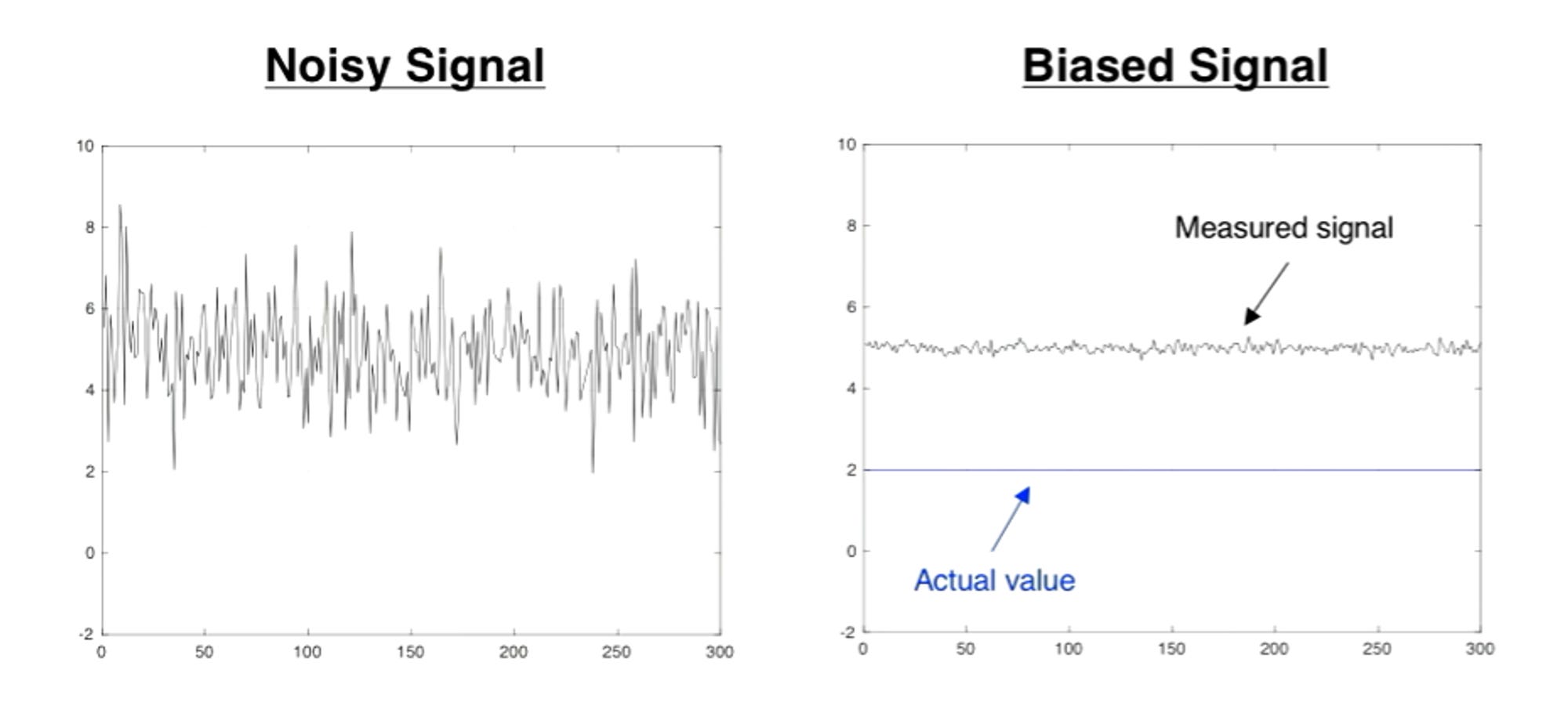
Signals have noise and/or bias which can corrupt your signal and give you inaccurate sensor data. To improve our sensor data we do 2 things.
Amplifying sensor output to appropriate voltages to be read by the microcontroller. Amplification happens with op-amp circuits and reducing voltages using a voltage divider or voltage regulator.
Reducing noise (low pass filter) and bias (high pass filter) in an output signal. Noise is when you have a high fluctuation in frequency. Bias is when your actual value is 2, but we measured at around 5.
There are 2 types of sensors, analog and digital. Analog sensors create signals when quantity is sensed, while digital sensors produce signals when performing a measurement. For my purposes, I would be using an analog signal to constantly get a signal for my device. This means the microcontroller will read the analog signal using an analog-to-digital converter (ADC).
Low Pass filters Remove high-frequency content from the signal. For mechatronics devices, this manifests in the form of high-frequency noise. There are 2 types of low pass filters
Type 1: Passive low pass filter
Known as an RC (resistor and capacitor) circuit. Passive circuit meaning it does not need to get powered. Schematic below.
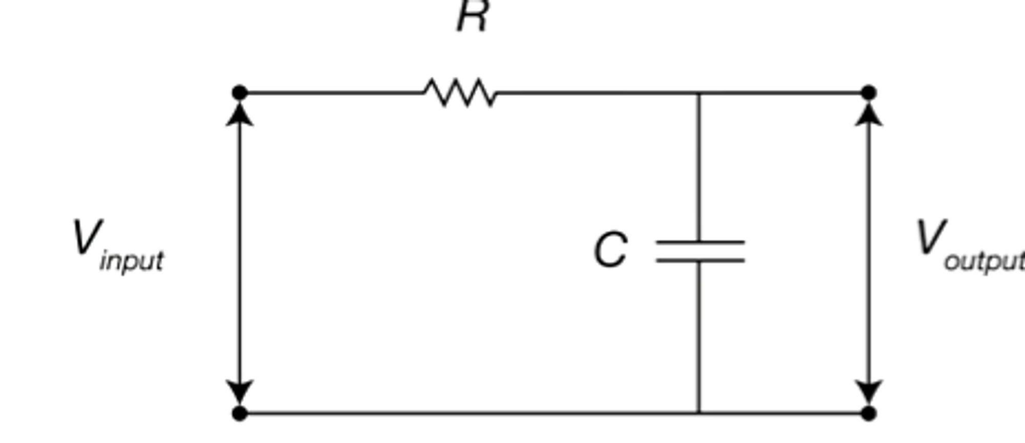
The filter time constant represented with the Greek letter τ (tau) is the resistance * capacitance or T = R * C
Type 2: Active low pass filter, here we use an op-amp circuit that amplifies and filter the input signal. Filter time constant is T = R2 * C.
The amount the signal is amplified is called a filter gain G=R2/R1.

A higher T value means more noise is removed, but there is a lag. A lower T value means less noise is removed, but there is less lag. Example below.
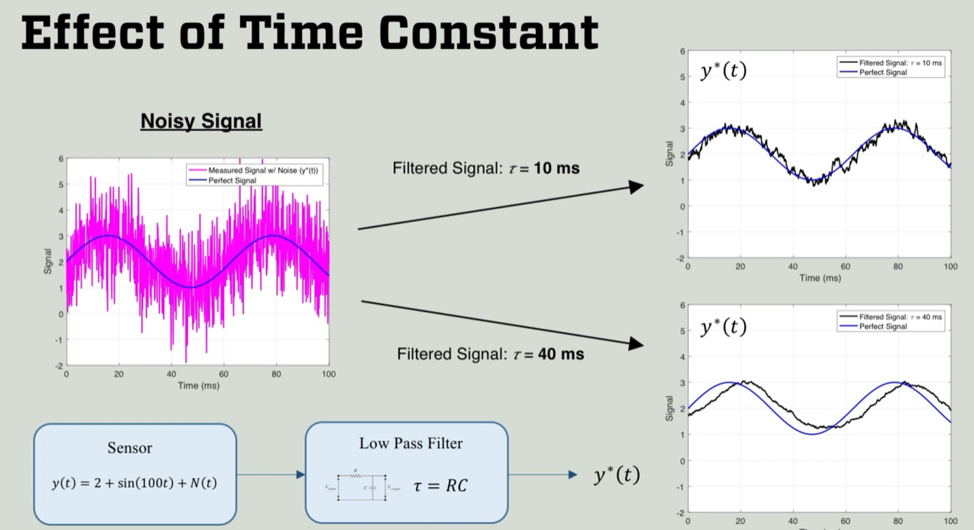
The value with high Tau represents a better signal but has some time lag. Depending on the application you would pick a low Tau or higher tau value. For applications that don’t need instant real-time feedback to function, you would use a filter with a higher tau value. This low pass filter can be implemented in software instead of circuitry.

High Pass Filters
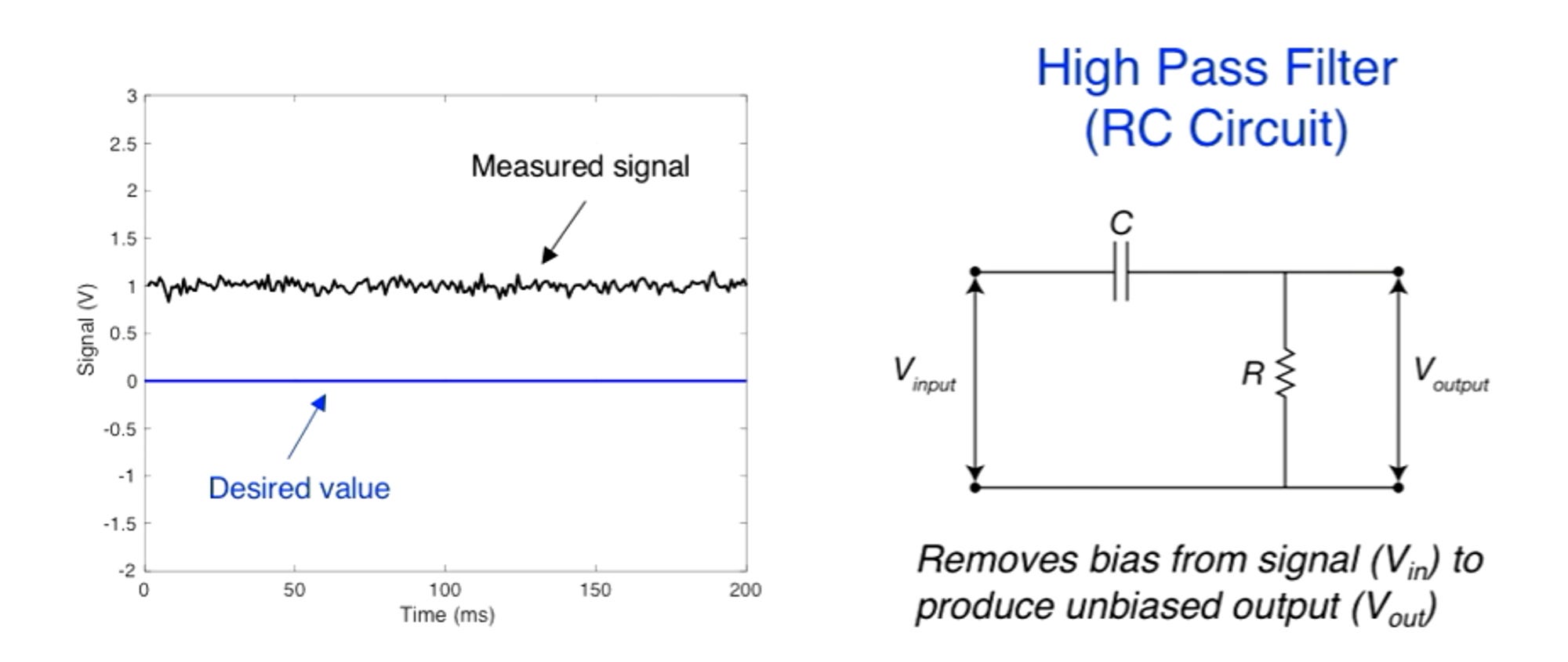
Sometimes you have a DC bias which is a fixed voltage offset. For example, the sensor produced 1V output when reading input of zero. To do that we use a high pass filter (RC circuit) the key difference is your switched the position of the capacitor and resistor compared to low pass filter circuitry.
Key Specifications For Sensors
Sensor range: a physical quantity that can be measured by a sensor (ex. temperature).
Sensor accuracy: the difference between true and measured values. Expressed as a percentage of full scale (FS) maximum value. It can be improved through calibration. The process has you take a measurement with your sensor, compare it to a reference standard, and write code to offset the difference.
Sensor sensitivity: the relationship between measured input and output of output. Most sensors have a linear relationship. Below is an example of a linear relationship with a sensitivity of 330mV/g. This value is helpful when reading voltage levels on a microcontroller to tell us how many g’s of acceleration your system is experiencing.

Sensitivity is called the scale factor or sensor gain. Below is an equation to relate input to output.

Sensor resolution: smallest change in the input that will produce an observable change in output value. This is true for digital sensors since they produce a digital signal only when performing a measurement. Most analog sensors don’t have a resolution, since they give continuous output. Resolution depends on the configuration of an analog-to-digital converter (ADC).
Purpose of Analog to Digital Converters (ADC)
Goal in reading analog voltages with microcontrollers. The problem with only reading digital values (from digital sensors) is you can only detect digital high (over 2V) and digital low (under 0.8V), but the voltage measurements in between are unaccounted for. ADC (a hardware device) can fix that problem.
If we had an 8 bit ADC and a range of 0 - 3.3V. 0V would be 8 bits with a value of 0 (e.g. 00000000) and 3.3V would be 8 bits with a 1 value. Voltage values in between would be mixture between 0 and 1. Voltage numbers between 0 and 3.3V would be mix between 1 and 0 for the 8 bits.
Operating Principle of Analog to Digital Converters
ADC works based on using a sample and hold circuit. Clock rates of ADC affect measurements.

By using ADC to measure analog signals you can select a sampling rate, which is how accurately you capture the characteristics of the signal.

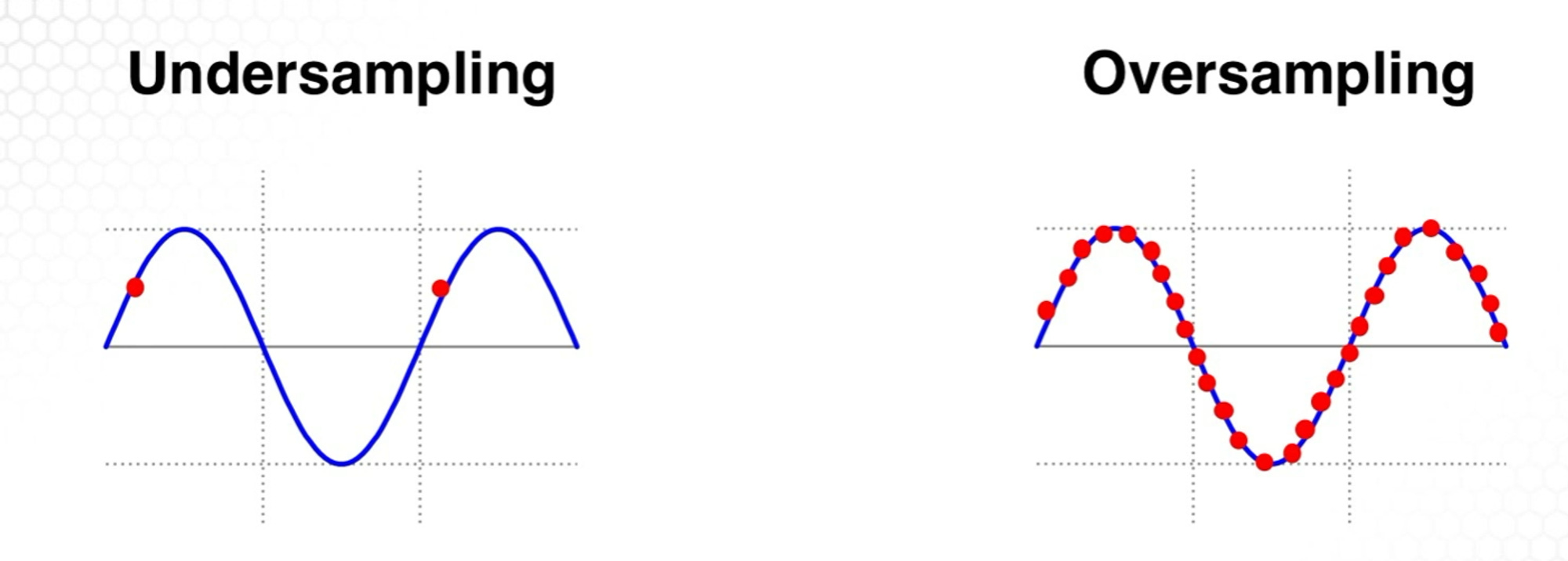
What you want to do is have enough sampling points to be able to correctly identify the shape of the wave. Below are examples of undersampling and oversampling. In undersampling, our slow detection can lead us to think that we have a straight line. Oversampling allows us to know that there was a sin wave, but it is not memory efficient.
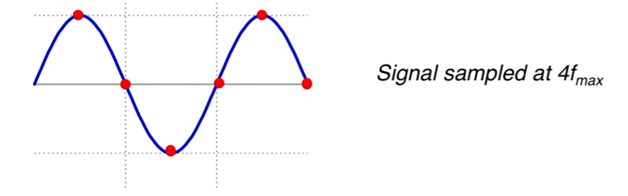
To fix the sampling problem we use the Nyquist sampling theorem, which says you must sample at a greater frequency 2* frequency (2f) to represent the signal. Frequency = 1/time. We then go through trial and error until we have a decent representation of the wave. The goal behind the theorem is to minimize memory use.
Most microcontrollers have built-in-in ADCs.
ADC Specifications
Range: Voltage range of ADC (ex. 0 — 3.3V)
Resolution: Smallest distinguishable difference in input (ex. 0.15mV)
Precision: Number of values ADC output can take on (ex. 256 for 8-bit ADC)
Clock speed
Range (volts) = Precision (# of alternative values) and Resolution (volts).
Resolution is determined by the range and precision. If we use more bits to represent a voltage range, then we have a higher resolution. If we use larger voltage range and keep the number of bits constant, we have a smaller resolution. Formula for computing a resolution of ADC.

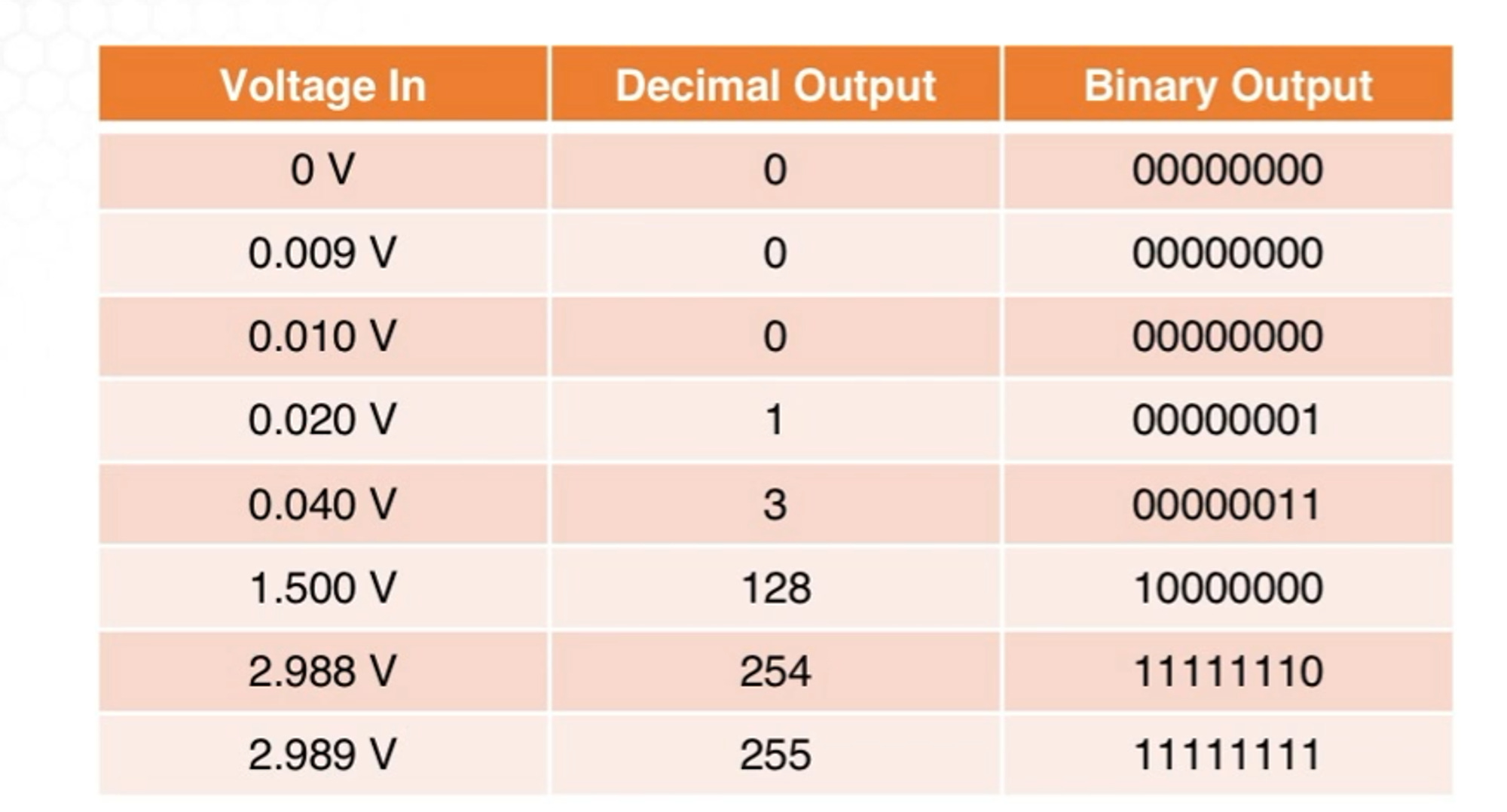
Example: 8-bit ADC with a range of 0-3V. 3-0/2^8-1 = 0.0118V. Below is the output of voltage in binary output.
Binary Numbers and Decimal Numbers
Digital computers are made from transistors. Since they usually operate in on and off states, that makes your computations act in a binary way. The number we normally use are represented by base 10. Think of the number 235, we say it as two-hundred and thirty-five or 200 + 30 + 5.

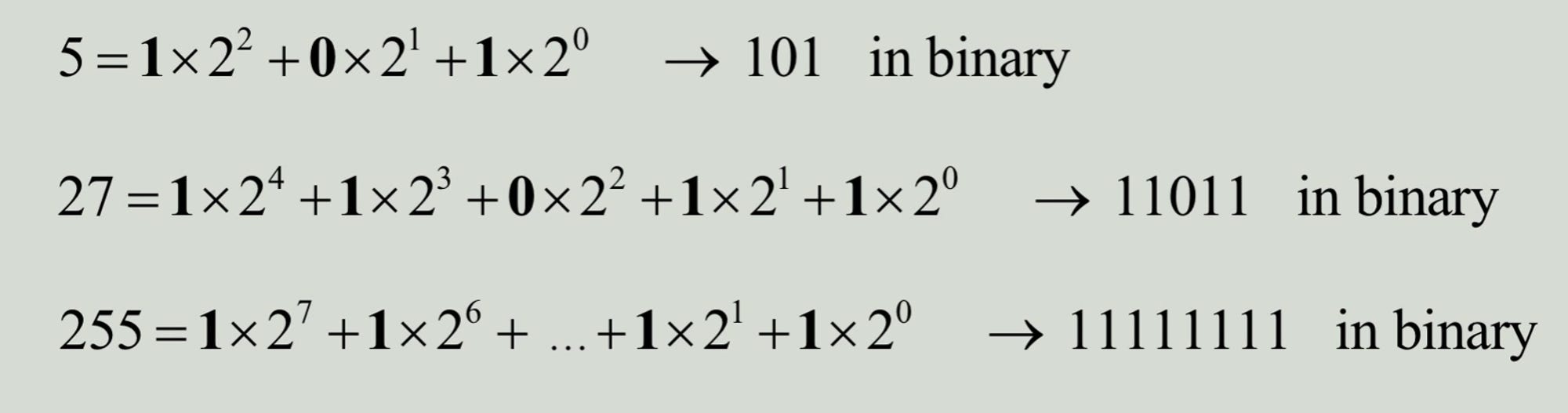
The computer thinks in base 2 because there has a binary operating system (0 or 1). Below are examples of how a base 10 number is turned into a base 2 binary number.
Placeholders in binary numbers are called bits (mix between binary and digit). A group of 8 bits is called a byte. Groups of two bytes is a word and a group of 4 is a double word.
2 Important terms. The most significant digital (MSB) represents the bit that represents the highest power of 2 and the least significant bit (LSB) which is the opposite. Example below.
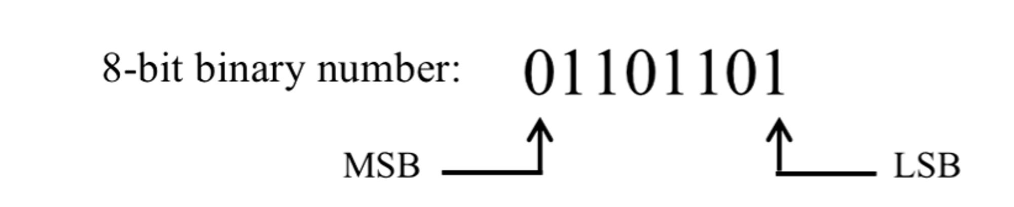
MSB and LSB are important for understanding the process of data transfer from an MCU to a computer.
For a given voltage range every extra bit approximately doubles the resolution.

Note: ADCs are only available in an even amount of bits. 9 and 11 bits are there for sake of example.
There is a trade-off between resolution (in bits) and conversion time. As you increase resolution, you increase your conversion time. Below is a table with the resolution and clock speed tradeoff.

For applications that require a fast sampling rate, you would reduce you would want to reduce your conversion time. If your application does not need the fastest sampling rate then you have a higher bit system to have more specific measurements.

You would start with equation below.

Range (volts) = Precision (# of alternative values) and Resolution (volts).
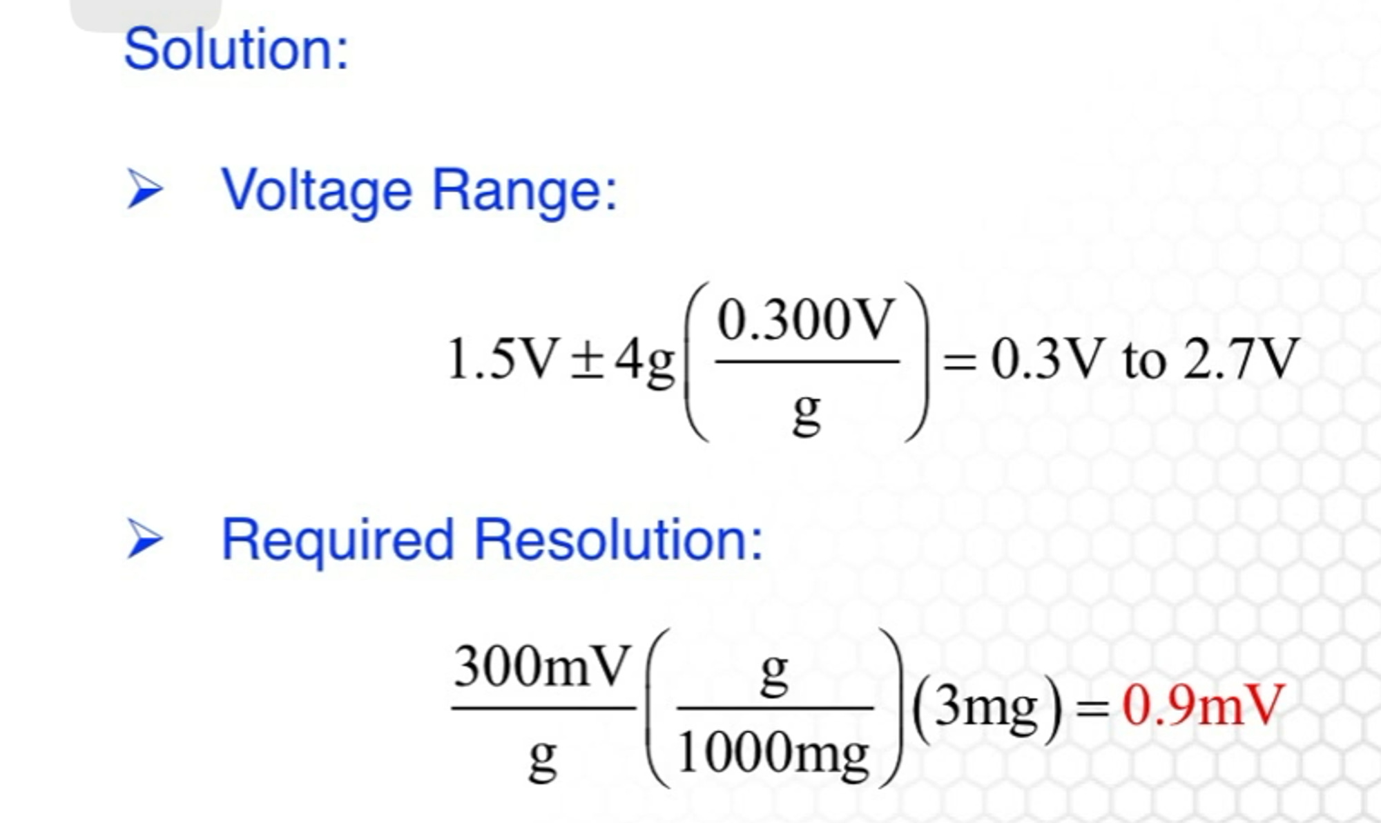

2.4V/0.009V + 1 = 267.6
2^8 = 256 This means that our bit size needs to be above 8. Since an odd number of bits are not available we would buy a 10-bit ADC.